In the world of automotive gauges, not all speed senders are created equal. There are two primary types you’ll come across: Sine Wave and Square Wave, and with modern technology the GPS signal sources now enter the mix as well. Whether you’re building a race car, restoring a classic, or upgrading to an AutoMeter electronic speedometer, understanding the differences between these senders is key to accurate performance.
What Type of Sender Does Your AutoMeter Speedometer Need?
The simple answer is – all are good options.
AutoMeter electric speedometers are designed to operate with both sine wave and square wave signals, as well as GPS-based senders. However, keep in mind that the more pulses per revolution (PPR) your sender produces, the smootheryour speedometer needle will move.
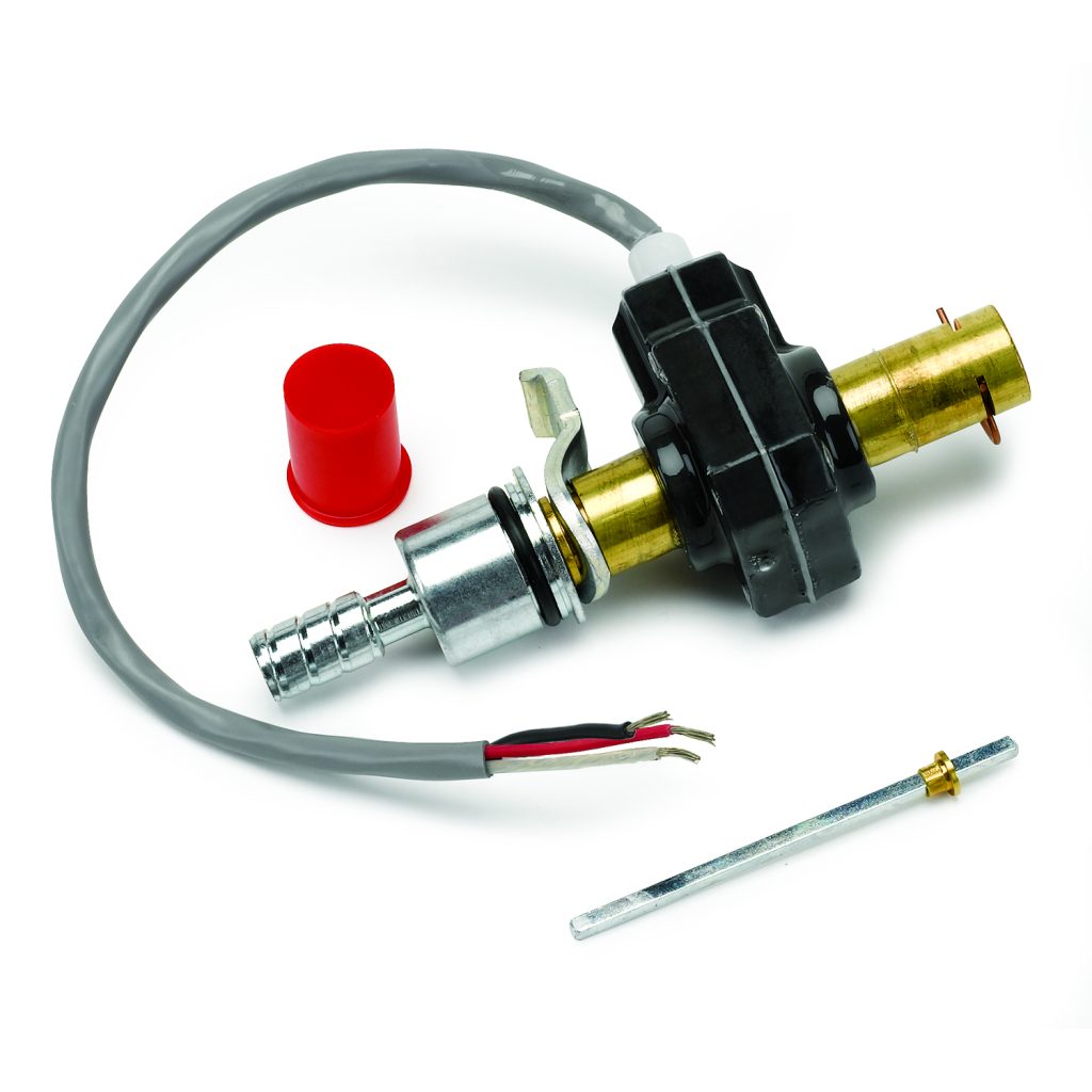
Square Wave Senders (Hall Effect)
A Square Wave sender, also known as a Hall Effect sender, is typically a three-wire sensor that requires:
- Power
- Ground
- Signal output
This type of sender produces an on/off digital signal, visible as square waves with zero volts as the base when viewed with an oscilloscope. Square wave senders are considered reliable and precise, making them ideal for retrofitting vehicles that previously used a mechanical speedometer cable.
At lower speeds, square wave senders also offer consistent signal quality, maintaining clear and stable output regardless of vehicle speed.

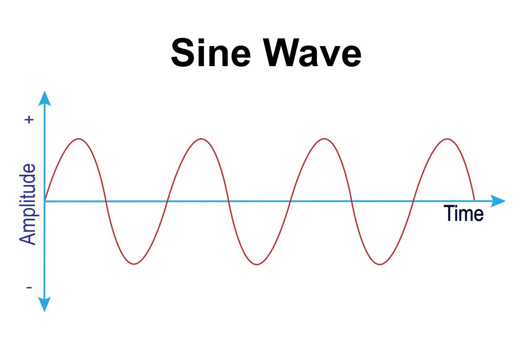
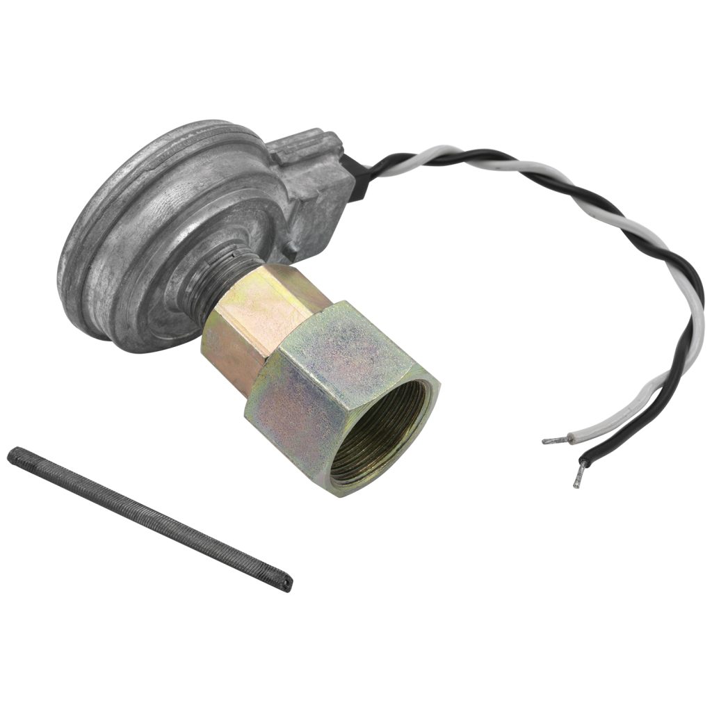
Sine Wave Senders (AC Generators)
A Sine Wave sender is typically a two-wire sensor, which only requires ground to one of the two wires. The opposite wire is your signal output.
You may ask; what if there is no power or even a 5V reference? How does that work?
Unlike a Hall Effect sender, it doesn’t require external power because it generates its own AC signal. As the sensor spins or passes magnetic flags, it creates an alternating voltage. The faster it turns (or metallic flags passing by it), the higher the voltage and frequency of the signal.
When viewed with a scope, it will look similar to a Square Wave (to the untrained eye), but will be rounded, and will also go above & below 0 (see below):
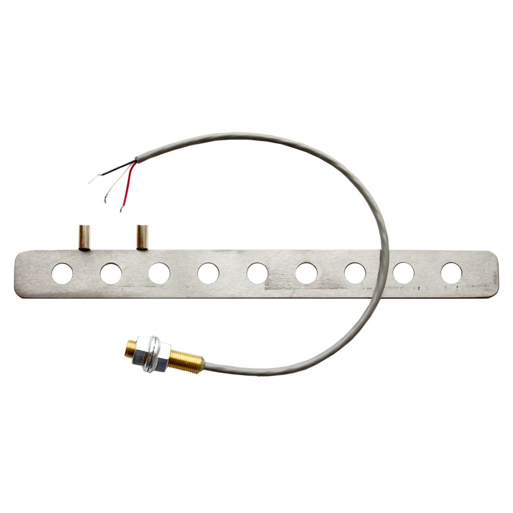
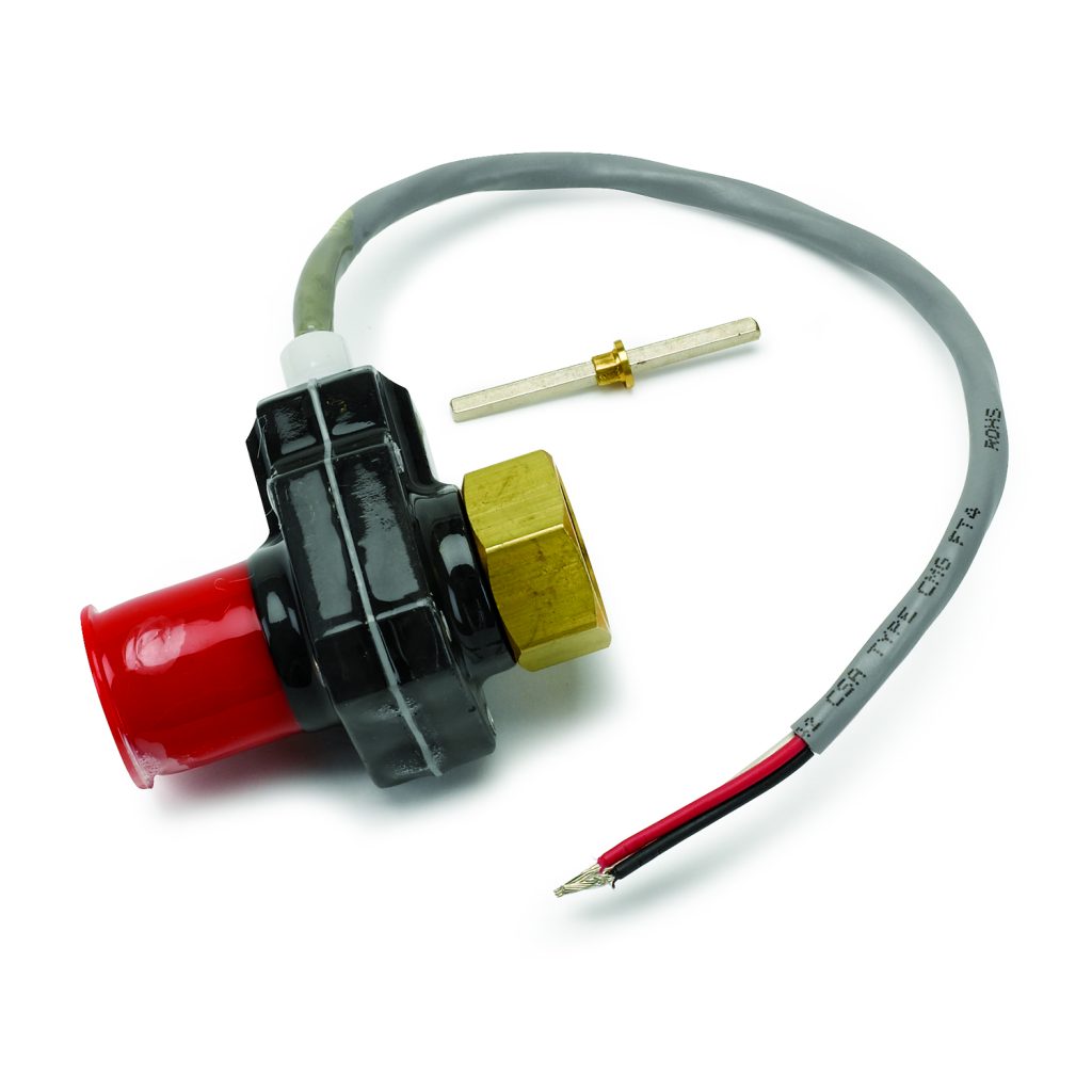
Shown below are both types of senders. You can tell each type by the number of wires:
AutoMeter Speedometer Signal Requirements
AutoMeter speedometers are compatible with:
- PPM (Pulses Per Mile): 500 up to 400,000
- Square Wave Voltage: Output of 5.0V to 16V (peak)
- Sine Wave Voltage: Output of 1.4VAC up to 120VAC (peak-to-peak)
Regarding PPM, this refers to “Pulses Per Mile”. Many senders (including our own) are often sold as “x” number of pulses per revolution. For example, the 5291 Hall Effect (square wave) speed sender is 16 pulses per revolution. A question we often receive is, “Why don’t we sell it as how many PPMs?”. The answer is simple – we don’t know your vehicle specifications, therefore, you will have to do some math beforehand if you want to know the PPM. Keep in mind that the following details will all influence the final PPM number:
Which Sender Is Better?
Both sender types will work with AutoMeter speedometers, but there are pros and cons to each.
Hall Effect (Square Wave) Sender
Pros:
- More consistent signal at low speeds
- Clean, stable digital output
- Ideal for retrofits replacing mechanical cables
Cons:
- Slightly higher cost
- Requires you to run a power wire to the sender, which is one more wire that the Sine Waver version requires
Sine Wave Sender
Pros:
- Simple two-wire design
- No external power required
Cons:
- Must reach a certain speed to generate a readable signal
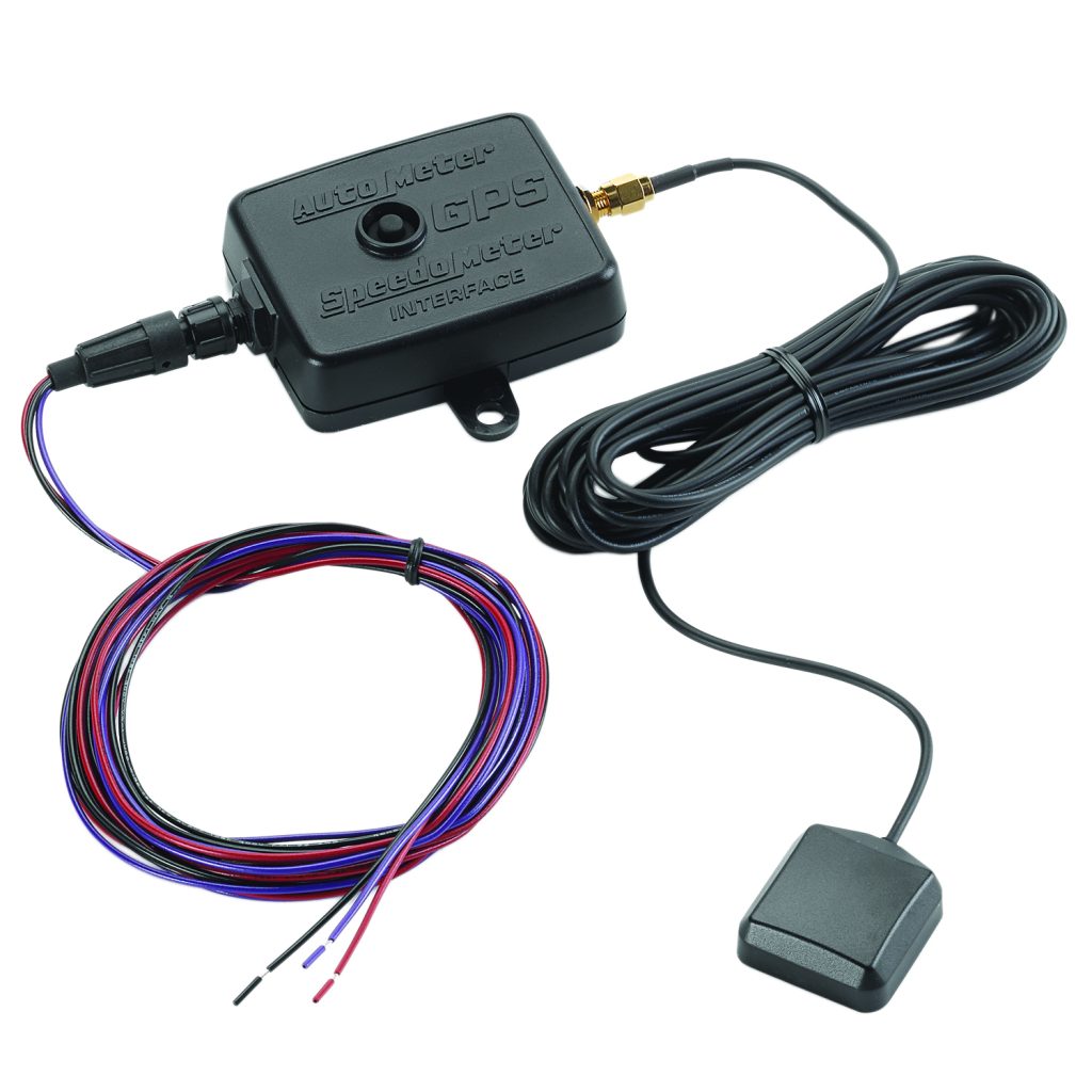
GPS Speed Senders
The AutoMeter GPS Interface Module outputs a 12V square wave signal, allowing modern GPS data to drive your electronic speedometer. Unlike mechanical or magnetic senders, the GPS module features programmable calibration. You can fine-tune it by holding the calibration button until the gauge reaches 80 mph, then letting it return to zero to lock in the setting. The unit will drop back to zero mph and is now calibrated to match your speedometer.
Compatibility with OEM or Other Brands
AutoMeter speed senders may work with non-AutoMeter speedometers, but always verify with the Square Wave, Sine Wave, and the voltage requirements and the frequency (PPM) requirements of your system before connecting. Some OEM senders only require 5V, 8V, 9V, or 12V input. Applying the wrong voltage can cause permanent damage.
Sender vs. Sensor: What’s the Difference?
In this context, the terms sender and sensor are interchangeable. A sensor typically feeds a computer or control module (PCM/TCM/ECM/EDU), or any other engine or transmission control module. However, a sender is used to output to a gauge. In either case, both provide a frequency signal proportional to vehicle speed and a voltage (AC or DC).
AutoMeter Speed Sender Reference
| Model | Type | Description |
| 5289 | GPS Interface | Model produces 12V square wave output |
| 5290 | Square Wave Speed Sender | Uses magnets – Universal for shaft speed (such as drive shaft) |
| 5291 | Hall Effect (Square Wave) | Speed sender for 7/8” threaded application |
| 5292 | Hall Effect (Square Wave) | Speed sender for Ford push-in style application |
| 5293 | Sine Wave | Speed generator for 7/8” threaded application |

Related Instructions and Resources
- AutoMeter Hall-Effect Speed Sender: 2650-1168.pdf, 2650-1634.pdf
- AutoMeter Sine Wave Speed Sender: 2650-1955.pdf
- AutoMeter GPS Interface Module: 2650-1570.pdf
- AutoMeter Electric Speedometer Calibration: 2650-1266.pdf


